multimeter
With the multimeter it is possible to carry out measurements of the
electrical quantities
mentioned above and in some multimeters there are also functions
such as: temperature in Celsius and Fahrenheit, semiconductor (diode) test,
conductor continuity
test and Duthy Cicle
signal percentage. Now let's see how to use it on several occasions.
Using the Multimeter
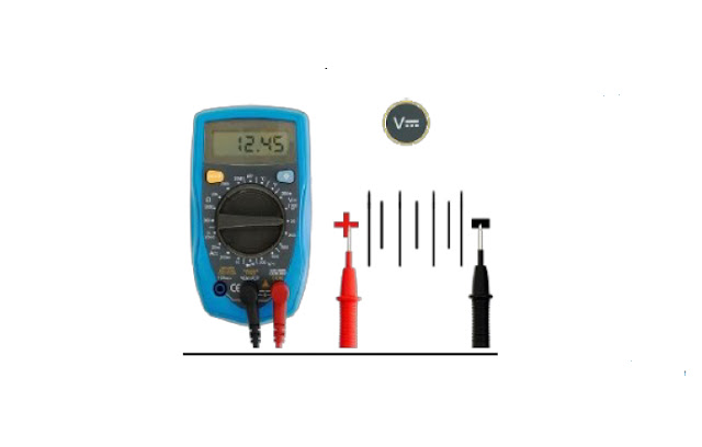
To measure direct current voltage we must:
Place the multimeter on the Continuous Voltage scale.
Place the probes correctly in the source that we want to measure
the Voltage, positive side red tip, negative side black tip.
To measure Diode and Continuity of a conductor we must:
To Measure Electric Current we must:
Open a consumer's electrical circuit
Place the red tip at the end of the circuit
that is open and the black tip at the other end as shown in the
figure.
Note: Current Test must be done for a maximum of ten seconds if for
a maximum
current of ten amps.
Oscilloscope
Using the Oscilloscope
The oscilloscope is an essential piece of equipment in the repair
of electronic centrals, as with it it is possible to diagnose the traffic of
electrical signals in the electrical circuit. For example; with it we can
identify if the processor is sending a coil's firing pulse, if this pulse is
leaving the responsible component and if
it is reaching the switch's nozzle connector.
Now let's see how we can use the oscilloscope and what are its most
important settings. With this understanding it will be possible to interpret
any signal on any oscilloscope.
Interpreting the Oscilloscope
Before reading the measured waveform parameters, we have to check
what the value of the time base adjustment and the voltage scale are
configured. In the example below we have:
Time base: equals 10 ms per division. It means that the horizontal
scan takes 10 ms to scan the space of a horizontal division of the screen.
Voltage range: 5V per division. It means that a variation of 5V in
the input signal corresponds to a vertical division of the screen.
So, we can conclude that:
The signal amplitude is (2 divisions) x (5V per division) = 10V.
The negative pulse width is (1 division) x (10 ms per division) =
10 ms.
The positive pulse width is (2 divisions) x (10 ms per division) =
20 ms.
The period is (3 divisions) x (10 ms per division) = 30 ms.
Adjusting the Oscilloscope
Oscilloscopes basically have 4 main settings:
Offset.
Time base.
Voltage scale.
Trigger Offset.
We can make the X axis of the drawn waveform be in the center of
the screen or in
another position as per our convenience.
time base
With this setting we can choose the speed of the screen's
horizontal sweep. Note that in both measurements the period of the waveform is
30 ms.
voltage scale
With this setting we can choose which input signal voltage value
will be represented by each vertical division of the screen. Note that in both
measurements the voltage amplitude value is 10 V.
trigger
The trigger (Trigger) is a feature that synchronizes the
oscilloscope's time base with the measured signal, preventing the trace from
sliding horizontally. This makes the trace drawing of the measured waveform
stable on the screen. The figure below illustrates a measurement with the
trigger misconfigured and, on the right, the same measurement with the trigger correctly
configured. With the trigger active, the oscilloscope stops drawing the
waveform every time the sweep reaches the far right of the screen and only
starts drawing the new trace if the trigger event occurs. This causes the
waveform to always be drawn from the same point. The trigger event occurs when
the measured waveform reaches the value and direction (ascending or descending)
determined by the user.
Common Wave Types
With the Oscilloscope we can observe the electrical signal in its
minimum and maximum amplitude, observe the cycles and frequency with which the
signal occurs, in addition to analyzing the integrity of this signal (if there
are no interruptions).


